Just a Picture to explain bgp peering : If you want more explaination in the simplest way possible?


Just a Picture to explain bgp peering : If you want more explaination in the simplest way possible?
download all notes , link is given below
privacy concern
Download link given at the end of this page
– Each and every Command explained beautifullyin detail
– A must have reference guide for all network engineer out there and CCIE RnS aspirants, – I recommend you to download the pdf book and you can make your own modified more detailed workbook or reference notes from this gift book

Download link :
I’m going to discuss with you today, the carrier supporting carrier “CSC” as in the previous post, we talked about how to connect VPN in two different locations from two different…
:
I am just giving an high level overview of the technology. I think it must be like less word with more explanation of the contents and concept.
At the end i have attached a pdf file of Cisco Validate Design for CAMPUS NETWORK. you can find the configuration part of technology discussed below in pdf file.I hope it will be useful to u.

Ok let’s Begin the discussion…
It all started with VLAN. As i have already told you the discussion will done in fewer and fewer word as far as possible.
by creating VLAN at Switch we actually are visualizing our L2 Domain by creating different broadcast domain in a one switch and trunk link further extend the design to Isolated path for each vlan domain from one switch to another switch..


and through Trunk Link multiple VLAN information/traffic can be carried over to another switch

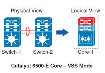
and here is the hardware virtualization:
Redundant Route Processor in a single Physical device
Redundant Line card
Redundant Power Supply
on Demand switch module add/remove


there we have many Physical L2 Switches are clustered which can be logically represented as a single switch (max 9 Switches can be stacked)
Mostly used at access layer , to provide high port density and one control or management plane.

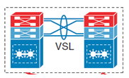
two Physical L3 Switches clustered to represent one logical switch
two of such switches can be connected through Virtual Switch Link (VSL) to function as a single Switch
So,
From VLAN – Trunk Link – Virtualization in switch Hardware ie
the Virtualization moves on to L3 domain (Router) from Switch only
In router in place of VLAN we have VRF
we can map VLAN traffic to VRF then it can be extended to whole campus network like vlan traffic can be extended to another switch through trunk link similarly VRF can extend it across routers in network .

because of the time constrain i am unable to give you configuration explanation but tomorrow i will post the discussion thoroughly.
and download link for best practice Cisco Validate Design for CAMPUS NETWORK is given below:
download link CVD :beloW
i think it is enough as an brief intro


SW1#sh run int fa1/1
interface FastEthernet1/1
  description SW1 to SP1
  switchport access vlan 10
end
SW1#sh run int vlan 10
interface vlan10
ip address 10.10.10.1 255.255.255.0
end
Next we need to get SP1 interface facing the customer in a q-in-q mode and assign a metro-tag. In this case I assigned metro-tag 510.
SP1#sh run int fa1/1
interface FastEthernet1/1
  description SW1 to SW4 dot1q
  switchport access vlan 510
!!VLAN 510 above is commonly referred to as metro-tag or customer tag.
  switchport mode dot1q-tunnel
!!Notice that we also tunnel cdp, stp, and vtp as well.
!!Normally they would not be by default
  l2protocol-tunnel cdp
  l2protocol-tunnel stp
  l2protocol-tunnel vtp
  no cdp enable
end
Now we need to configure the interfaces between the Service Providers which is just a basic trunk.
SP1#sh run int fa1/2
interface FastEthernet1/2
  description connected to SP2
  switchport trunk encapsulation dot1q
  switchport mode trunk
end
SP2#sh run int fa1/2
interface FastEthernet1/1
  description connected to SP1
  switchport trunk encapsulation dot1q
  switchport mode trunk
end
The interface on SP2 facing the customer side is assigned the same metro-tag of 510.
SP2#sh run int fa1/3
interface FastEthernet1/3
  description SW4 to SW1 dot1q
  switchport access vlan 510
  switchport mode dot1q-tunnel
  l2protocol-tunnel cdp
  l2protocol-tunnel stp
  l2protocol-tunnel vtp
  no cdp enable
end
We need to configure the customer equipment to put the interface facing the service provider on VLAN 10.
SW4#sh run int fa1/3
interface FastEthernet1/3
  description connected to SP2
  switchport access vlan 10
end
SW#sh run int vlan 10
interface vlan10
ip add 10.10.10.4 255.255.255.0
end
Let’s see what happens when we ping from SW1 to SW4.
SW1#ping 10.10.10.4
 Type escape sequence to abort.
 Sending 5, 100-byte ICMP Echos to 10.10.10.4, timeout is 2 seconds:
 !!!!!
 Success rate is 100 percent (5/5), round-trip min/avg/max = 8/10/12 ms
SW1#
Let’s see what CDP shows.
SW1#show cdp neighbors
 Capability Codes: R - Router, T - Trans Bridge, B - Source Route Bridge
          S - Switch, H - Host, I - IGMP, r - Repeater, P - Phone
 Device ID    Local Intrfce   Holdtme  Capability Platform  Port ID
 SW4          Fas 1/1            142       R        3550    Fas 1/3
SW1#
As you can see it appears as though SW4 is connected directly to SW1. What is really happening is that VLAN 10 traffic is double tagged with VLAN 510. In other words VLAN 10 is encapsulated in VLAN 510 and sent across to SP2 hence the q-in-q tunneling.
Side note — You will have to set the system mtu greater than 1500 on the SP1 and SP2 switches which does require a reboot to take effect. In the Cisco 3750s that I used the command to increase the system mtu is “system mtu 1546”
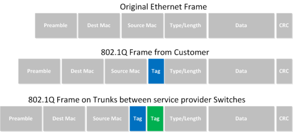
IEEE 802.1Q tunneling can be used to achieve simple layer two VPN connectivity between sites by encapsulating one 802.1Q trunk inside another. The topology below illustrates a common scenario where 802.1Q (or “QinQ”) tunneling can be very useful.

A service provider has infrastructure connecting two sites at layer two, and desires to provide its customers transparent layer two connectivity. A less-than-ideal solution would be to assign each customer a range of VLANs it may use. However, this is very limiting, both in that it removes the customers’ flexibility to choose their own VLAN numbers, and there may not be enough VLAN numbers (we can only use a maximum of 4,094 or so) available on large networks.
802.1Q tunneling solves both of these issues by assigning each customer a single VLAN number, chosen by the service provider. Within each customer VLAN exists a secondary 802.1Q trunk, which is controlled by the customer. Each customer packet traversing the service provider network is tagged twice: the inner-most 802.1Q header contains the customer-chosen VLAN ID, and the outer-most header contains the VLAN ID assigned to the customer by the service provider.

Before we get started with the configuration, we must verify that all of our switches support the necessary maximum transmission unit (MTU), 1504 bytes. We can use the command show system mtu to check this, and the global configuration command system mtu to modify the device MTU if necessary (note that a reload will be required for the new MTU to take effect).
S1# show system mtu
System MTU size is 1500 bytes
S1# configure terminal
S1(config)# system mtu 1504
Changes to the System MTU will not take effect until the next reload is done.
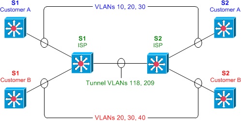
Next, we’ll configure our backbone trunk to carry the top-level VLANs for customers A and B, which have been assigned VLANs 118 and 209, respectively. We configure a normal 802.1Q trunk on both ISP switches. The last configuration line below restricts the trunk to carrying only VLANs 118 and 209; this is an optional step.
S1(config)# interface f0/13
S1(config-if)# switchport trunk encapsulation dot1q
S1(config-if)# switchport mode trunk
S1(config-if)# switchport trunk allowed vlan 118,209
S2(config)# interface f0/13
S2(config-if)# switchport trunk encapsulation dot1q
S2(config-if)# switchport mode trunk
S2(config-if)# switchport trunk allowed vlan 118,209
Now for the interesting bit: the customer-facing interfaces. We assign each interface to the appropriate upper-level (service provider) VLAN, and its operational mode to dot1q-tunnel. We’ll also enable Layer two protocol tunneling to transparently carry CDP and other layer two protocols between the CPE devices.
S1(config)# interface f0/1
S1(config-if)# switchport access vlan 118
S1(config-if)# switchport mode dot1q-tunnel
S1(config-if)# l2protocol-tunnel
S1(config-if)# interface f0/3
S1(config-if)# switchport access vlan 209
S1(config-if)# switchport mode dot1q-tunnel
S1(config-if)# l2protocol-tunnel
S2(config)# interface f0/2
S2(config-if)# switchport access vlan 118
S2(config-if)# switchport mode dot1q-tunnel
S2(config-if)# l2protocol-tunnel
S2(config-if)# interface f0/4
S2(config-if)# switchport access vlan 209
S2(config-if)# switchport mode dot1q-tunnel
S2(config-if)# l2protocol-tunnel
We can use the command show dot1q-tunnel on the ISP switches to get a list of all interfaces configured as 802.1Q tunnels:
S1# show dot1q-tunnel

dot1q-tunnel mode LAN Port(s)
-----------------------------
Fa0/1
Fa0/3
Now that our tunnel configurations have been completed, each customer VLAN has transparent end-to-end connectivity between sites. This packet capture shows how customer traffic is double-encapsulated inside two 802.1Q headers along the ISP backbone. Any traffic left untagged by the customer (i.e., traffic in the native VLAN 1) is tagged only once, by the service provider.

Purpose : Get layer 2 connectivity over ip backbone network b/w R1 & R4 representing two different sites
Lab : ethernet port/ethernet dot1Q vlan over L2TPv3 Pseudowire
It is a 3 step process
1. Create l2tp-class
2. Creat Pseudowire class
3. Linking Pseudowire to customer site facing inteface

Your site will be connected like they are directly connected to each other P2P
! Addressing :
R2-R3 23.1.1.0/24
R1-R2-R3-R4 Looback 0 interface ip address are 1.1.1.1 , 2.2.2.2 , 3.3.3.3 , 4.4.4.4
R1-R4 14.1.1.0/24 & Router Rip among them configured
R1
 conf t
 int ethernet 0/0
 ip add 14.1.1.1 255.255.255.0
 no shut
 !
 do wr
 !
 int loop0
 ip add 1.1.1.1 255.255.255.0
 !
 exit
 !
R1 & R4
 Router Rip
 ver 2
 net 0.0.0.0
 no auto-summary
 !
 exit
 !
likewise do configuration on R4, R3 & R2
description Pseudowire stitching configuration between R2-R3
description Pseudowire for –ETHERNET PORT–
 R2
 ip cef                                                 { : enable ip cef
 !
 l2tp-class R2-R3-CM                                    { : Create l2tp-class
 authentication
 password 0 1331
 !
 exit
R2
 pseudowire-class R2-R3Pwire     {:Create  pseudowire-class
 encapsulation l2tpv3            {:pseudowire encapsulation type - here is l2tpv3
 protocol l2tpv3 R2-R3-CM        {:choose pseudowire protocol -  here is l2tpv3
 ip local interface Loopback0    {:define which  interface involved in pseudowire
 !
 exit
 R2
 int e0/0                                                                               { : customer facing int
 no ip add
 xconnect 3.3.3.3 1004 pw-class R2-R3Pwire   {Pseudowire stiching VCID 1004

 !
 R3
 xconnect 2.2.2.2 1004 pw-class R2-R3Pwire    {other EnD
 !
show l2tun session { :check the pseudowire coonnection
!
R1#ping 4.4.4.4 source 1.1.1.1
if successful L2 connectivity among R1 & R4 has been done , L2VPN created !
::::: Pseudowire for –ETHERNET VLAN 802.1Q– (100 vlan number) :::::
R2
 !
 int e0/0
 no ip add
 no ip direct broadcast
 !
 int e0/0.1
 encapsulation dot1q 100
 xconnect 3.3.3.3 1004 pw-class R2-R3Pwire                      {:on R2 ingress
 !
R3

int e0/0
 no ip add
 no ip direct broadcast

!
 int e0/0.1 :on R3 egress
 encapsulation dot1q 100
 xconnect 2.2.2.2 1004 pw-class R2-R3Pwire                      {:on R2 egress
try to ping both end
R1#ping 4.4.4.4 source 1.1.1.1
if successful L2 connectivity among R1 & R4 has been done , L2VPN created !
